Category: Chassis
Frame Repair and Rear Suspension Continued..
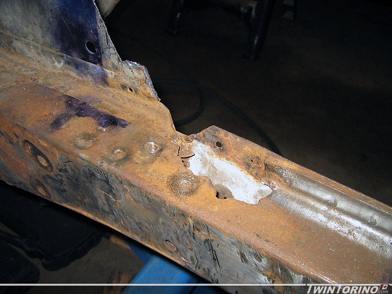
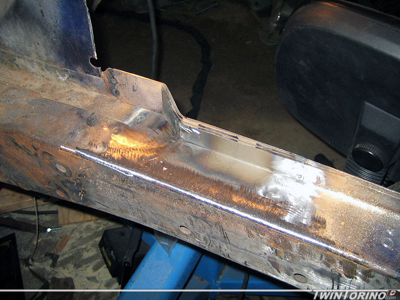
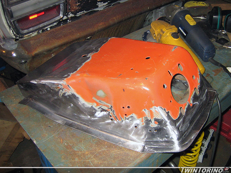
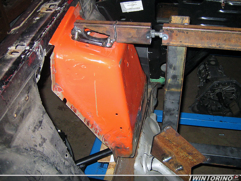
When we removed the shock towers the steel was flaking away a bit, but I thought it was nothing out of the oridinary. The more I picked away at it.. the bigger it got. Have to attack this before the towers go back in. Should last a couple more years now. This also brings up the question – how the heck do you get at this area if the stock towers are still in the car? Most people do not have the novelty we do by not having them in the way. Still have to fix the underside where the rest of the water went and rotted things away.
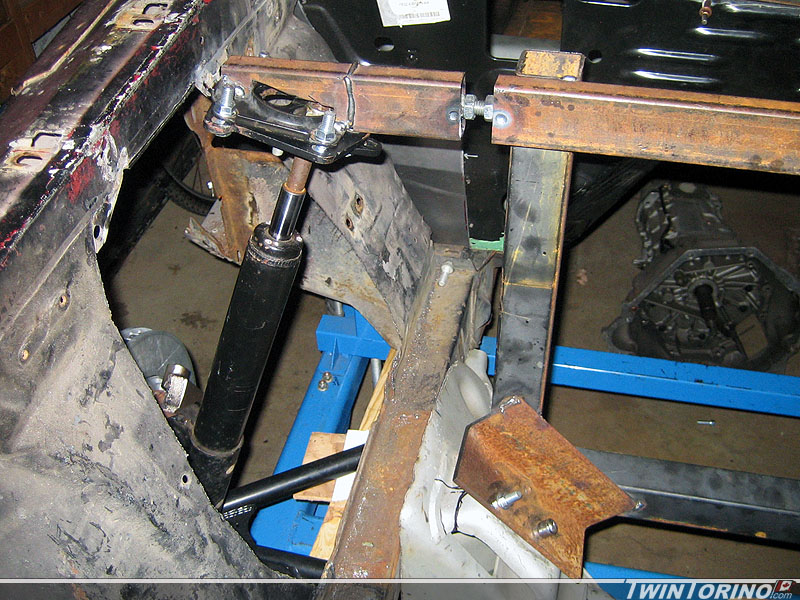
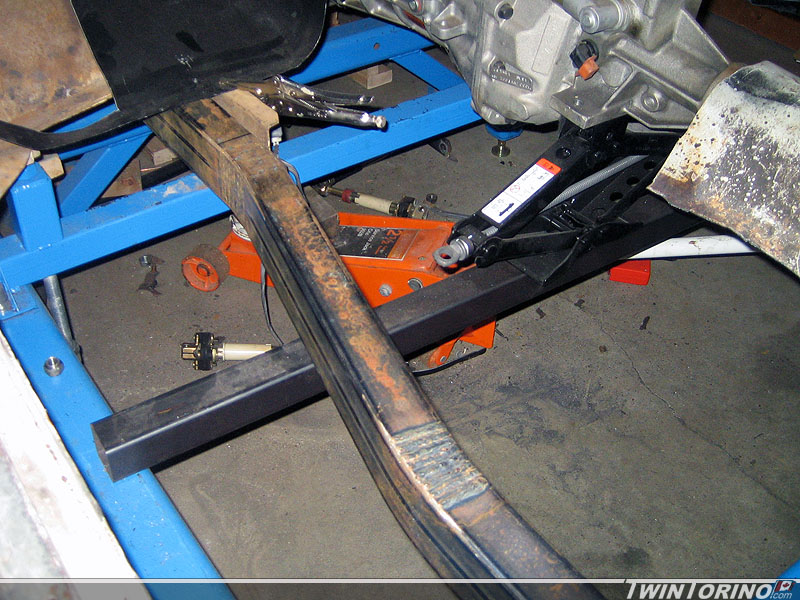
Since the front suspension is finishing up, time to move back to the rear once again. Had a lot of time to think about this one now, so time to put it in action. Biggest issue with designing anything in the rear is the tire clearance. Fitting the 315’s back there requires lots of room. Couple of constraints here – the outer fender lip since the tire will sit within it, the springs and the shocks. We went back and forth on coil over shocks, but in the end they are expensive and take up precious tire clearance. They also do not provide the most desirable load path as the shock mounting holes are outboard of the frame rail (many of the aftermarket kits out there use single shear mounts on the outside of the frame rail which we are not big fans of). The shocks even without the coil-overs will require notching the frame, although very minimally. The result here.. the springs and shocks will mount in separate locations like the stock Mustang.
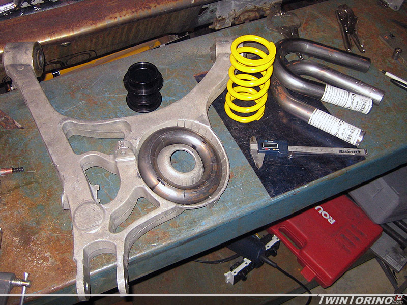
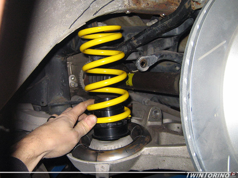
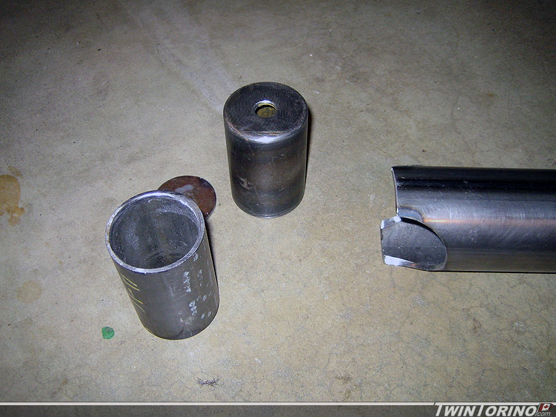
In the end, this is how we decided to mount the spring. We are using the stock spring pocket on the lower control arm, but using a much smaller spring. We started with 2 u-bends as you can see, and turned them into a doughnut. This way we maximize surface area to distribute the load. Just need to add a flat plate in the middle and a small wedge to angle the spring as required. Then we simply add a mount to the frame rail. Notice we are also adding an adjustable sleeve for fine tuning the ride height. Since we are running fairly stiff springs all around, we will be using helper springs (very low stiffness) to keep the springs in place when the suspension goes into full rebound.
Engine Cradle Continued
Couple more updates from the past week.
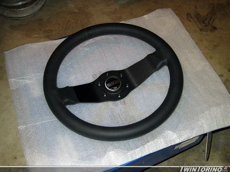
Finally found a steering wheel for the cars.. been looking for a while on this one. Two reasons for this choice: the style is “somewhat” similar to the original with the single horizonal bar, and secondly Sparco has been clearing out some wheels on Ebay cheap so this made them affordable too. We’ll see what it looks like in the car I guess. The model is called “Veloce” and is leather with the perforated leather strip at the top.
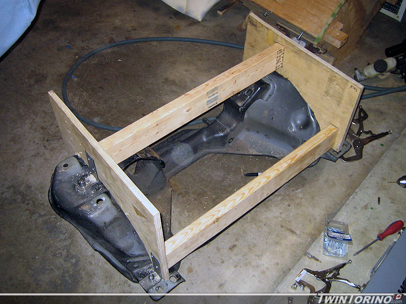
Moving right along on the front suspension. Pass side strut tower is done and ready to tack in. Next step was to make a perfectly centered and tight fitting k-member. The one we have been using to date is hacked up and really only for setting things up. Time to make another jig for this. As you can see, nothing too elaborate, but it serves it’s purpose. We used reference holes on the part used at the assembly plant to locate the jig. Then we made up 2×4’s that are the exact width between the frame rails. Finally two pieces of plywood are used to conform to the curves of the part. To use, the jig is placed on a Mustang K-member, sockets are placed in the 4 holes to located jig and then a utility knife blade is used to scribe lines on the parts. After that, we break out the plasma cutter and trim/grind to suit. Works like a charm! Making one for car #2 is now a breeze.
We used it to cut the k-member shown and it fits perfectly. That will make it very easy to weld in. Started on making up pieces to run under the frame rails to clean up the package and add a bit more stiffness. Kinda looks like the k-member was meant to be in there. Just need to make up the rear ones and the k-member will be ready to go in. Only thing left now is to weld in the filler panels and modify the motor mounts. After that, the front suspension is done!!
Shock Tower Camber Setting
Got some more work done on the shock tower setup. Unfortunately with the Fox control arms being used, this also means the upper strut mount needs to move inboard to be able to get the alignment settings right. This meant we needed to cut up the jig and make it adjustable using threaded rods and nuts.
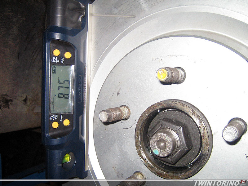
The goal here is to be able to set the front wheels to 2-3° of neg camber for the track, and then adjust them back to 0.5° neg camber for the street. The caster is also being increased relative to stock. Looks like 275’s will fit up front when using the 0.5° setting which is great news.
All that is needed to set things into position is to flip the camber plates upside down and swap side to side. This way they can be bolted to the jig. Next max the camber setting inboard and then take suspension measurements. Keep adjusting the fixture outboard until the max neg camber is achieved. After this, unbolt and put on shock towers. Lots more sheetmetal work ahead, but it should hopefully work out in the end. Turns out the inner surface of the shock towers is almost flush with the origional fram rail which make things easier fab wise.
Floors and Frame Connectors Continued
Finally located the parts that were missing from the second transmission. Someone decided to take it apart and just slap things back together when they realized it had issues. We fixed all the issues and everything is as good as new again. Trans #2 is now complete and ready to install.
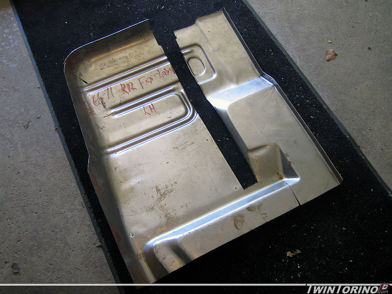
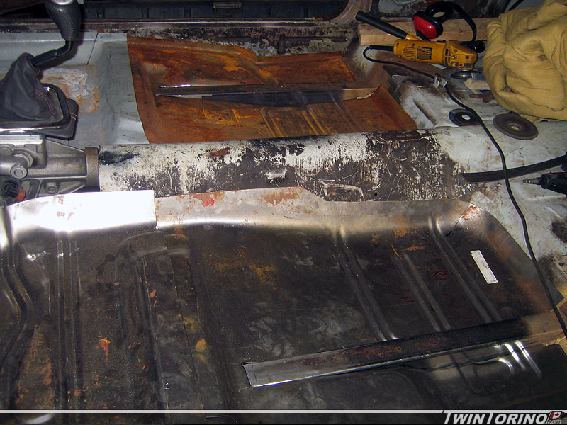
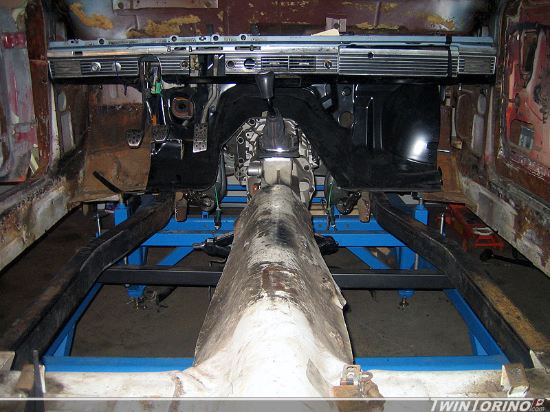
Now back to the interior once again. The top portions of the subframe connectors are now completely welded in, so it is time to finish up the firewall and the floors. The firewall was trimmed to fit around the torque box and was adjusted to the final position both side to side and up and down. The floor needed to be slotted to clear the subframe connectors both front and back. We ended up lowering the floor 3/4″ to get everything where we wanted it. Just need to add an inch or two to the front pan so it will mate up with the firewall. This works out great and will no longer require toe pans. I had to pull out the hammer and dolly set to get the profile of the front of the floor pan to match the firewall – worked out quite well in the end.
Just need to make up extensions for both sides of the firewall and make up a tranmission hump, then everything can be welded in for good. Finally starting to feel like we are getting somewhere. Hopes of being ready to drive for the Power Tour is out the door – but the Bash at the Beach is still in within reason.
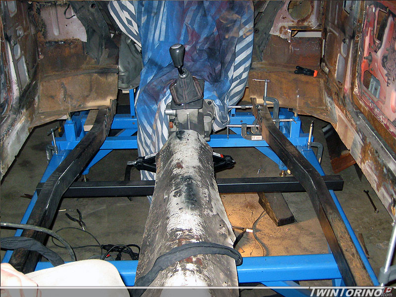
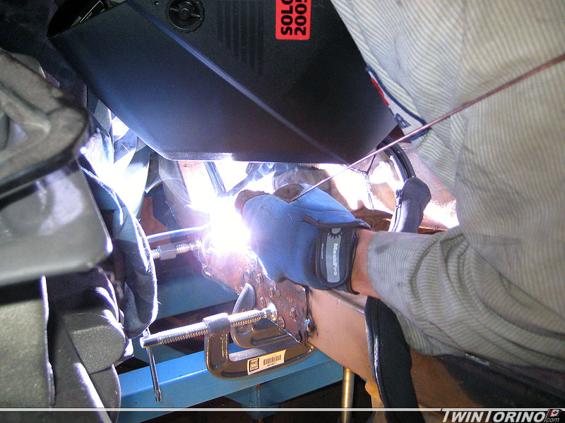
Subframe Connectors Tacked In..
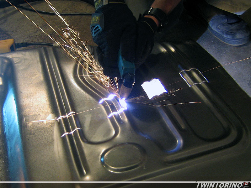
Got the subframe connectors clamped in and tacked into position. Coated everything with SEM copper weld through primer and started welding them in for good. Don’t think they are are going anywhere now :). The old transmission crossmember worked out perfect to stiffen these up and tie them into the subframe.
Suspension Brakes and Chassis Continue..
Made some more progress this week. Old trans mount brackets were modified so they now mate up with the subframe connectors. Once they are welded to the subframe connector – they should look like they are supposed to be there. This will also free up some room for the exhaust.
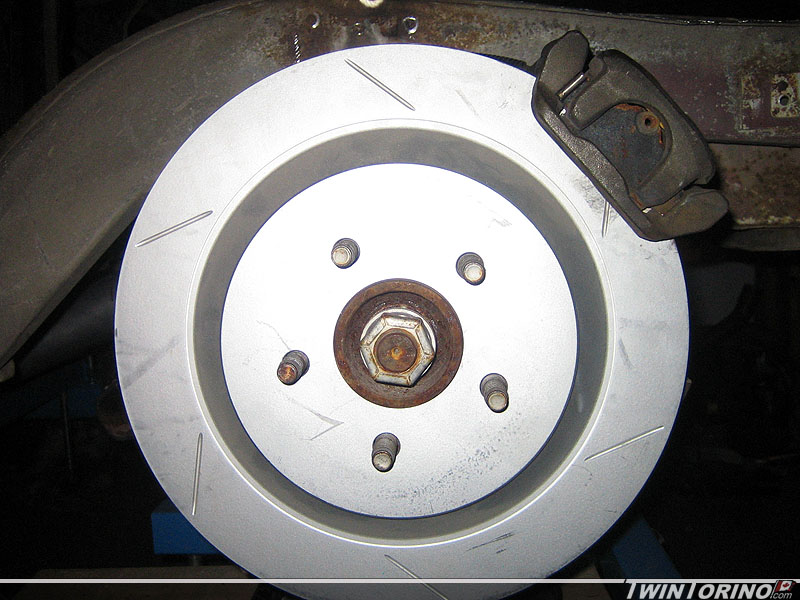
Driver’s and pass side connectors are now complete as well. Finished off the front IRS mounting bracket piece that fits into the old leaf spring pocket. Just need to be welded once everything is assembled on the vehicle. Also mounted up the rear 13″ rotors – as expected they need to mached to work in our applicaition (since they were designed for a car with Mustang GT brakes and not Cobra brakes). The caliper sits too high as you can clearly see.
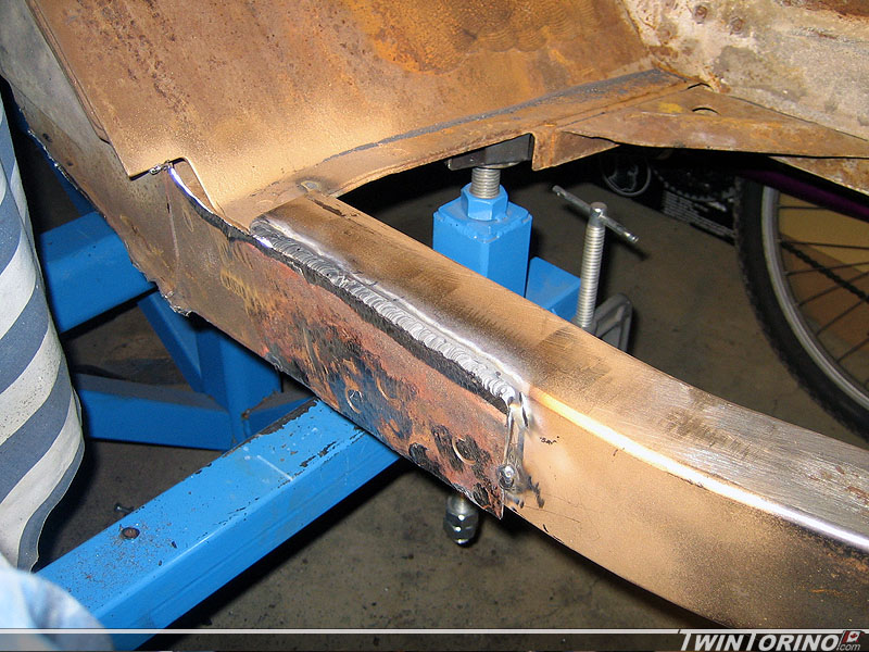
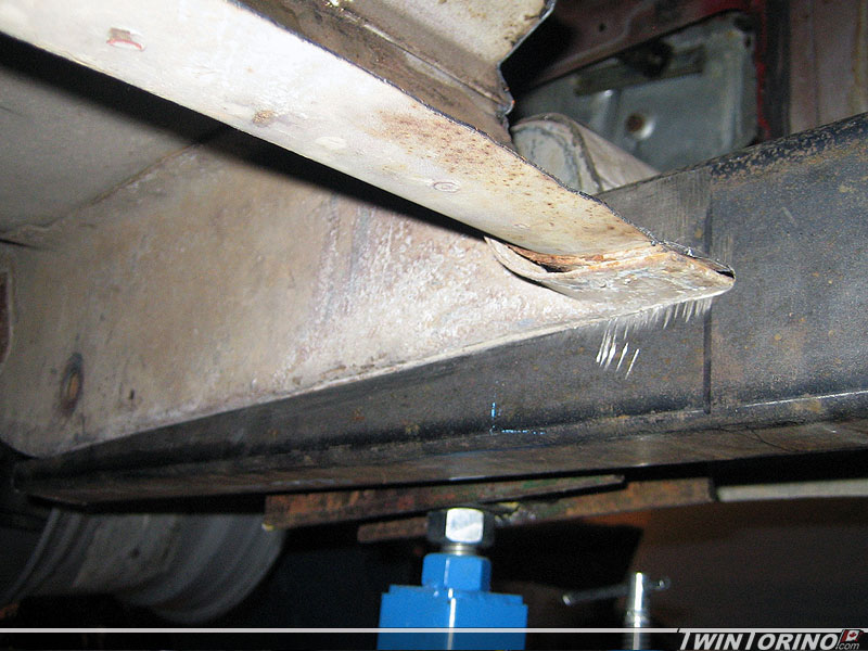
Subframe Connectors Conform to Body
Subframe connectors are now ready to weld in (finally). Just need to prep all the areas for welding now. Very happy with how they fit. There is lots of weld area to tie these into the existing front and rear subframes. Should increase the stiffness of the chassis quite a bit. If all goes well.. they should look they are supposed to be there. Also need to rework the brace that used to hold the trans crossmember so it sits flush with the subframe connector.
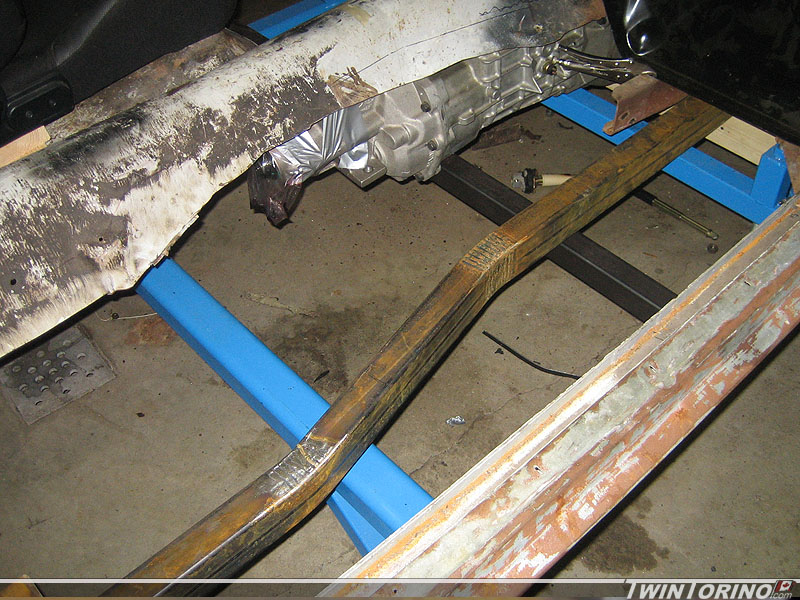
Subframe Connector Concept..
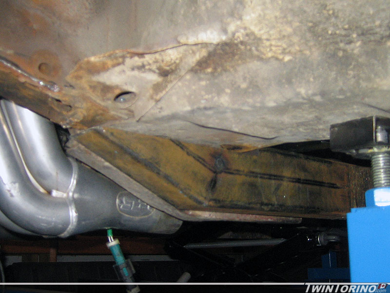
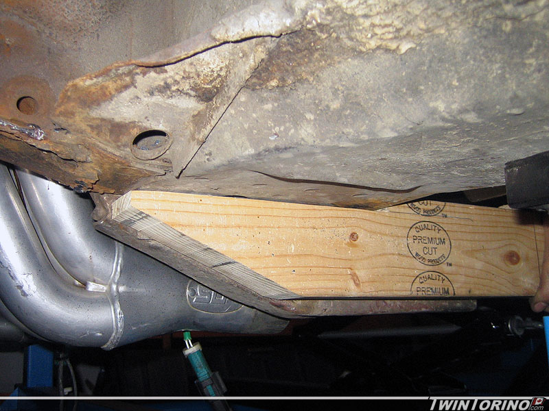
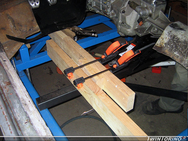
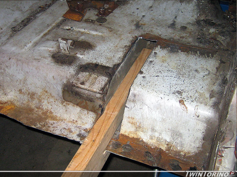
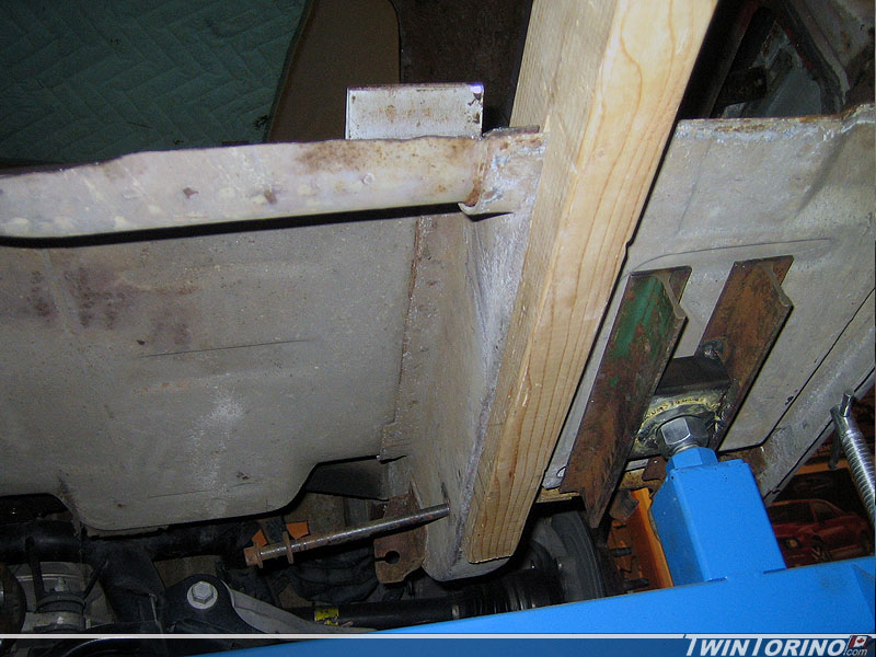
Made some more progress in the past week or two on the car. It was finally time to cut out the drivers side floor section to make room for subframe connectors and the new floors. Have the subframe connectors all figured out now. Used some 2×4’s to determine the overall diemsions and how to cut the steel. Came out quite nicely. Pictures can do the talking on these. As you can see – they tie directly into the rear frame rails (requiring cutting into the framerail area from above) and will also tie into the front frame rails. When all is said and done – they should look somewhat natural. Next comes cutting the actual connectors to shape and welding them in. To do this, a bandsaw was desirable so we ended up finding a broken one locally for $25 (wood/metal) so that should be up and running in the next couple of days.
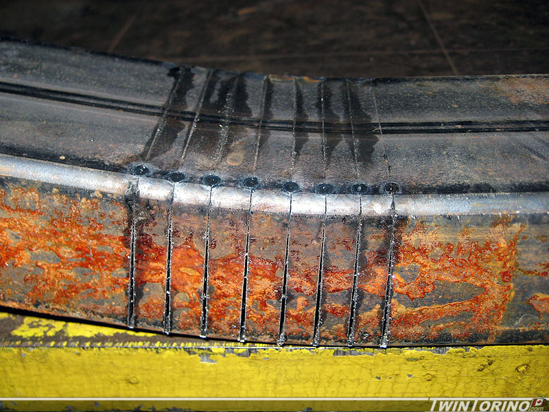
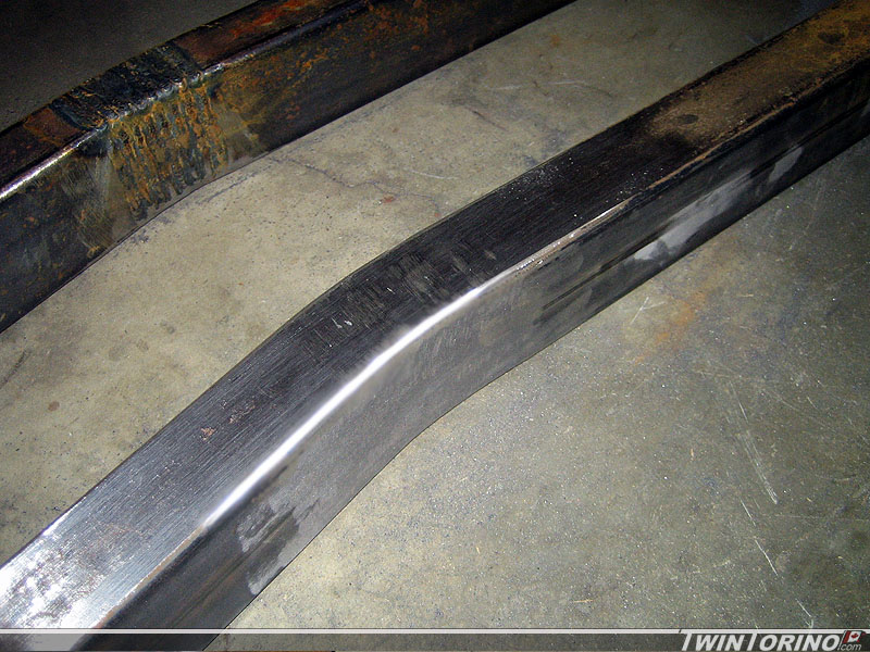
Subframe Connector Bend Welds..
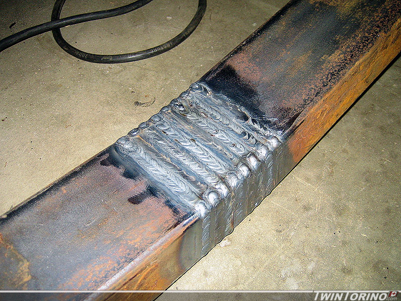
I finished up cutting and welding the second connector yesterday. Also started to grind away some of the weld to smooth the surface out. Very happy with the end result. Should be able to get them cut to length and start cutting up the floors to make them fit this week.
We also decided to go after a completely different braking system as I ran into a deal I couldn’t pass up. Pics to come this week.
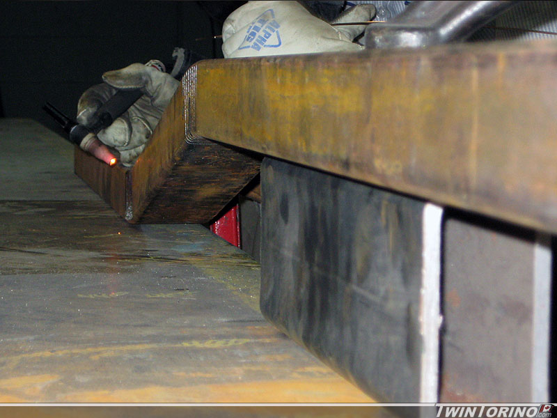
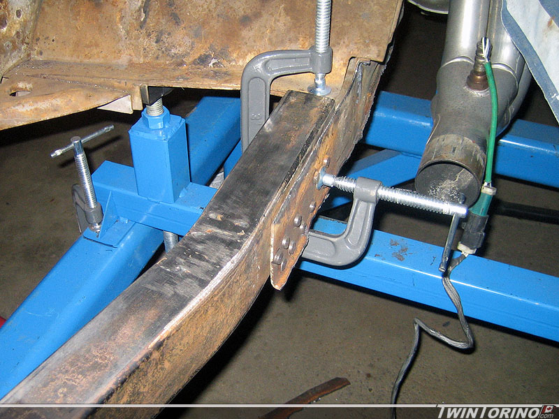
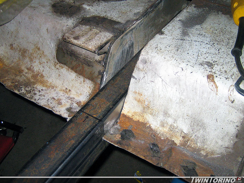
Subframe Connector Jog..
Finally making some progress on stiffening up the chassis. Since the floors are cut out, we decided to run a full connector from the front torque box / frame rail to the rear one. The goal here is to make it look like the frames connect to one another and make it appear factory installed. First problem with that idea is the front subframe is offset 4″ from the rear. We decided to add a 4″ jog into the part as shown below. This involves calculating the angle to bend the material, measuring the width of the bandsaw blade, and then making the necessary cuts to get there. Then lots of miles on the TIG to attached everything together again. It is a rather long process in comparison to just notching it out, but looks much cleaner (even though noone will likely notice once installed). Hard to explain what we are doing to connect them to the front or rear, so you’ll have to wait for pictures in the next couple of weeks :). I had to transport them in the snow between buildings on the weekend.. rust does seem to wait too long before appearing. Just need to clean up the welds bottom and sides and then the pieces will look like they were mandrel bent.