Category: Rear Suspension
Frame Repair and Rear Suspension Continued..
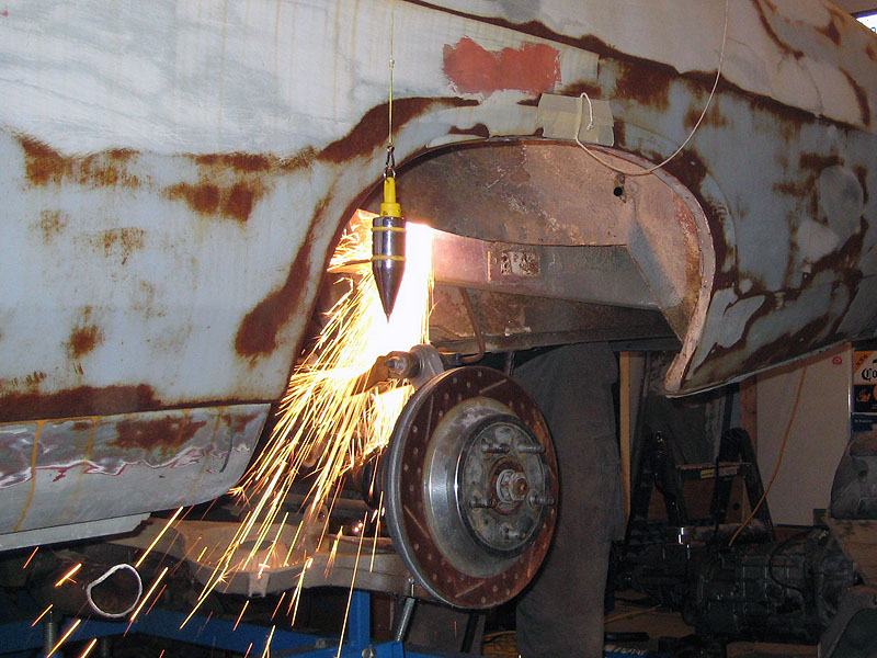
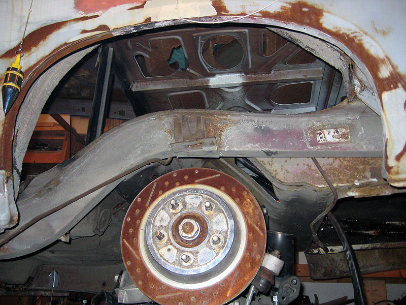
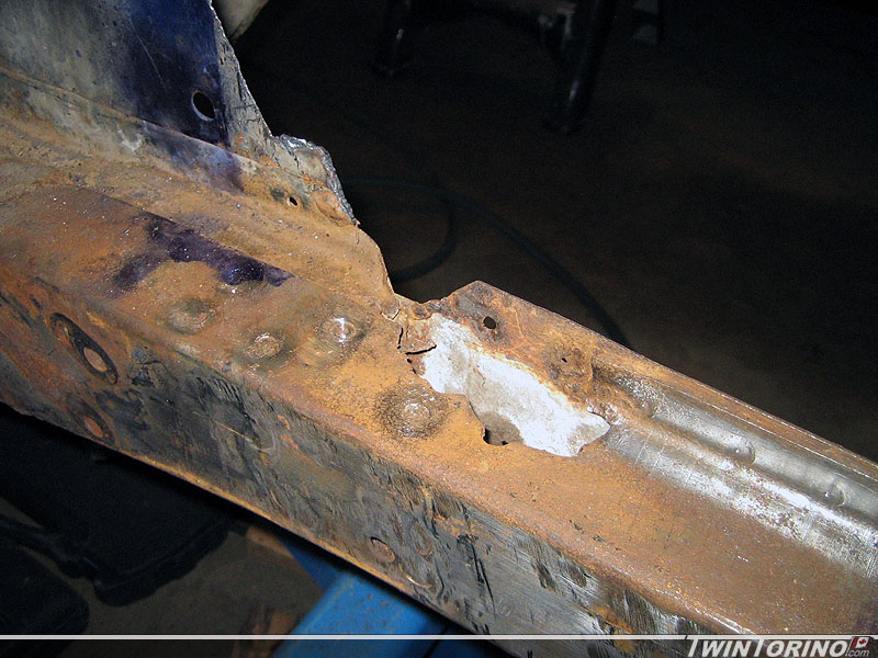
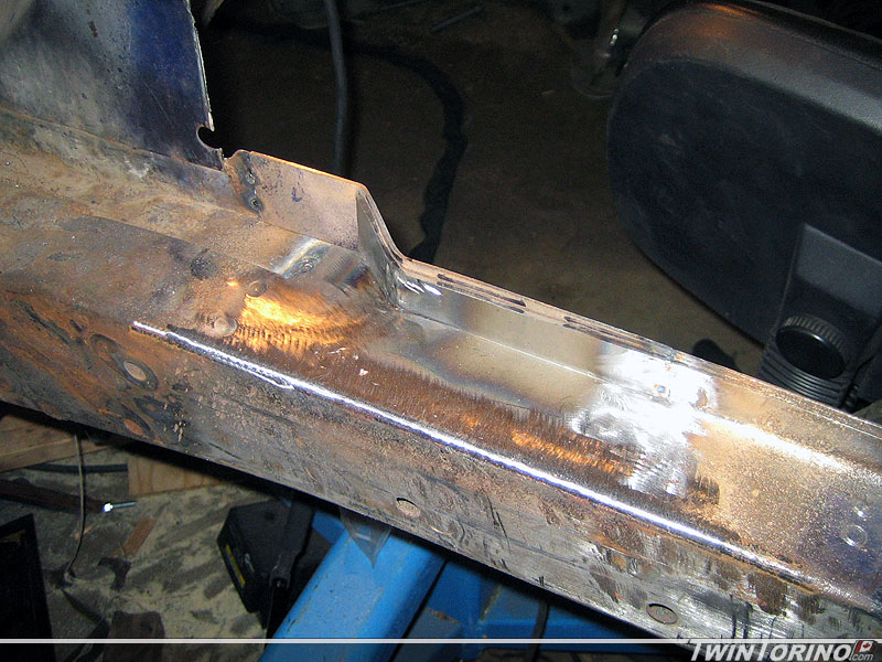
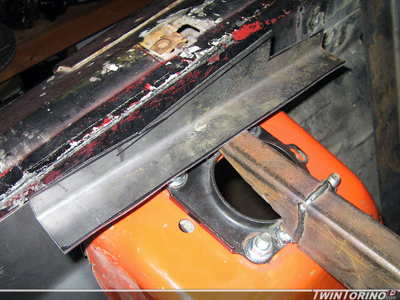
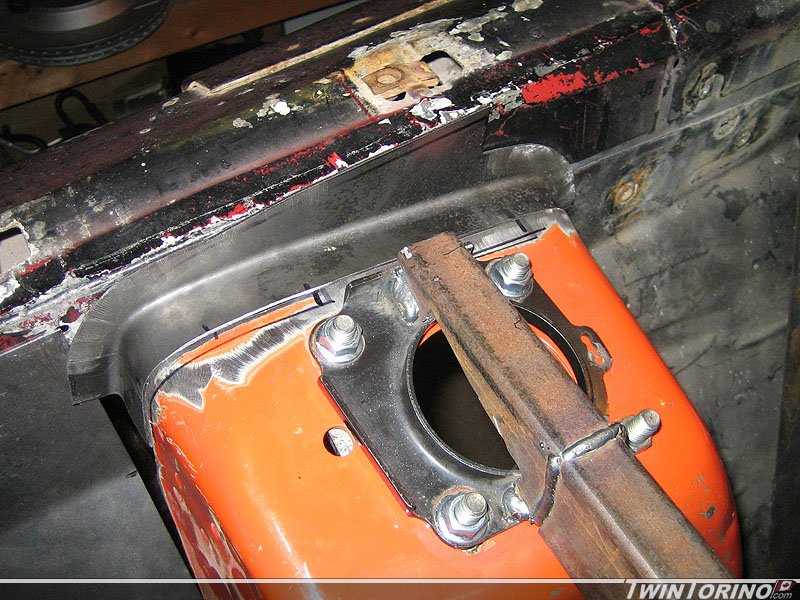
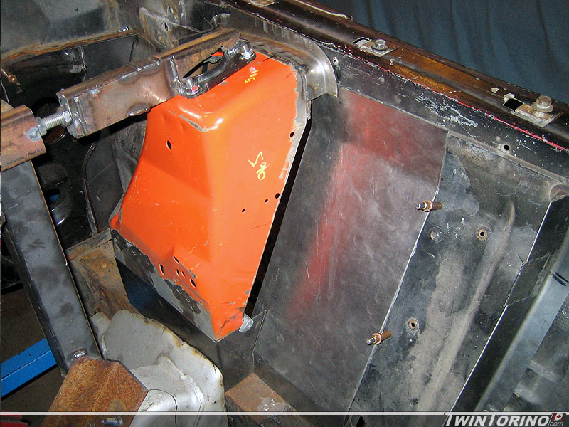
When we removed the shock towers the steel was flaking away a bit, but I thought it was nothing out of the oridinary. The more I picked away at it.. the bigger it got. Have to attack this before the towers go back in. Should last a couple more years now. This also brings up the question – how the heck do you get at this area if the stock towers are still in the car? Most people do not have the novelty we do by not having them in the way. Still have to fix the underside where the rest of the water went and rotted things away.
Since the front suspension is finishing up, time to move back to the rear once again. Had a lot of time to think about this one now, so time to put it in action. Biggest issue with designing anything in the rear is the tire clearance. Fitting the 315’s back there requires lots of room. Couple of constraints here – the outer fender lip since the tire will sit within it, the springs and the shocks. We went back and forth on coil over shocks, but in the end they are expensive and take up precious tire clearance. They also do not provide the most desirable load path as the shock mounting holes are outboard of the frame rail (many of the aftermarket kits out there use single shear mounts on the outside of the frame rail which we are not big fans of). The shocks even without the coil-overs will require notching the frame, although very minimally. The result here.. the springs and shocks will mount in separate locations like the stock Mustang.
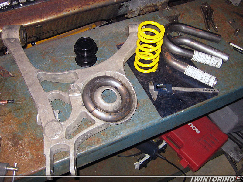
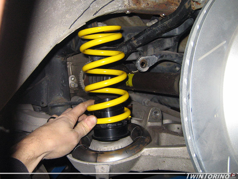
In the end, this is how we decided to mount the spring. We are using the stock spring pocket on the lower control arm, but using a much smaller spring. We started with 2 u-bends as you can see, and turned them into a doughnut. This way we maximize surface area to distribute the load. Just need to add a flat plate in the middle and a small wedge to angle the spring as required. Then we simply add a mount to the frame rail. Notice we are also adding an adjustable sleeve for fine tuning the ride height. Since we are running fairly stiff springs all around, we will be using helper springs (very low stiffness) to keep the springs in place when the suspension goes into full rebound.
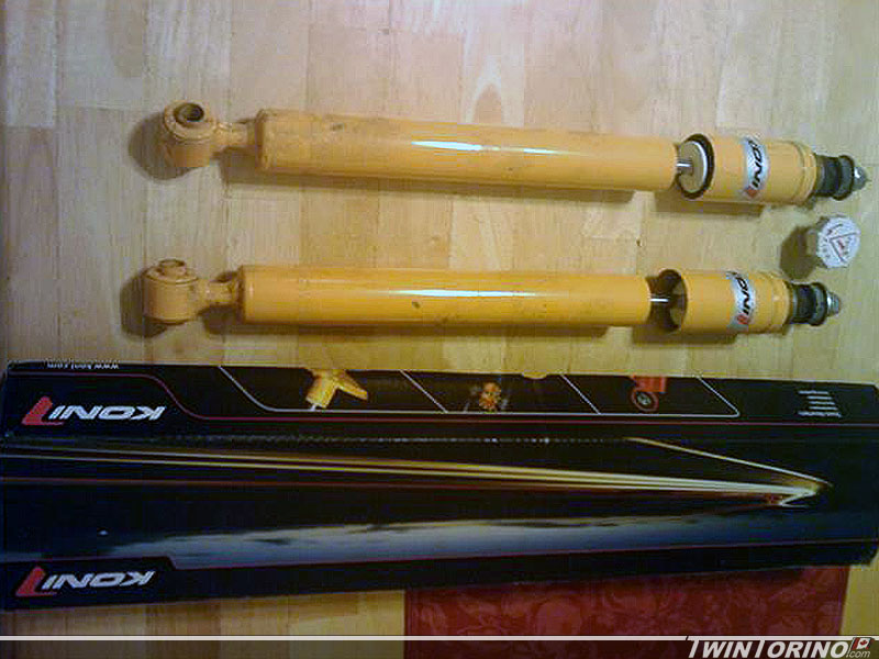
Got a couple more things done this week. Found a set of nearly new rear adjustable Konis specifically made for the IRS suspension. Just need to make some custom upper mounts.
Also got the pass side upper shock tower piece bent up. Stretcher shrinker combo works miracles with ease. Also got the drivers side upper piece tacked in, and worked on the front filler panel. Most things are almost ready to weld in.. but I ran out of Argon so I have to wait another couple of days to get the bottle filled.
Rear IRS Cradle Mounts and First Rotisserie Parts..
Almost finished the pass side front IRS mount. Getting closer and closer to sitting this thing on the ground – can’t wait. The front brackets are basically ready to weld in. These things will hopefully look factory installed when we are done.
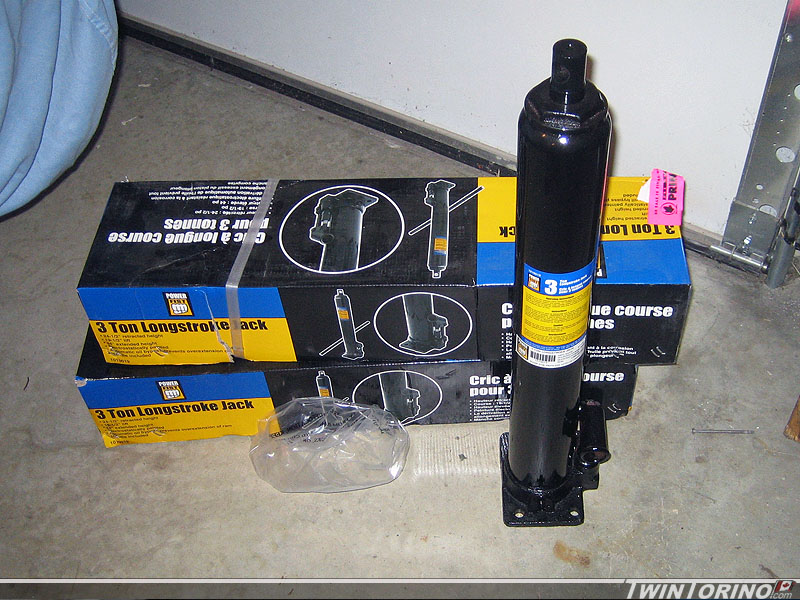
3 ton jacks finally went on sale at Princess Auto (Canadian version of Harbor Freight). This is the first step of getting th roisserie underway. We will be grabbing steel for it in the next couple of weeks. Hope to be building the rotisserie within the next month.
Front IRS Mounts…
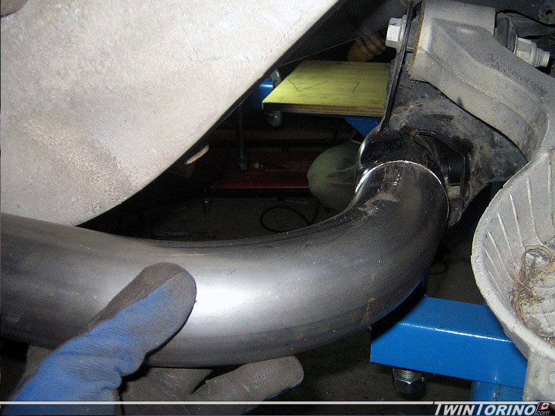
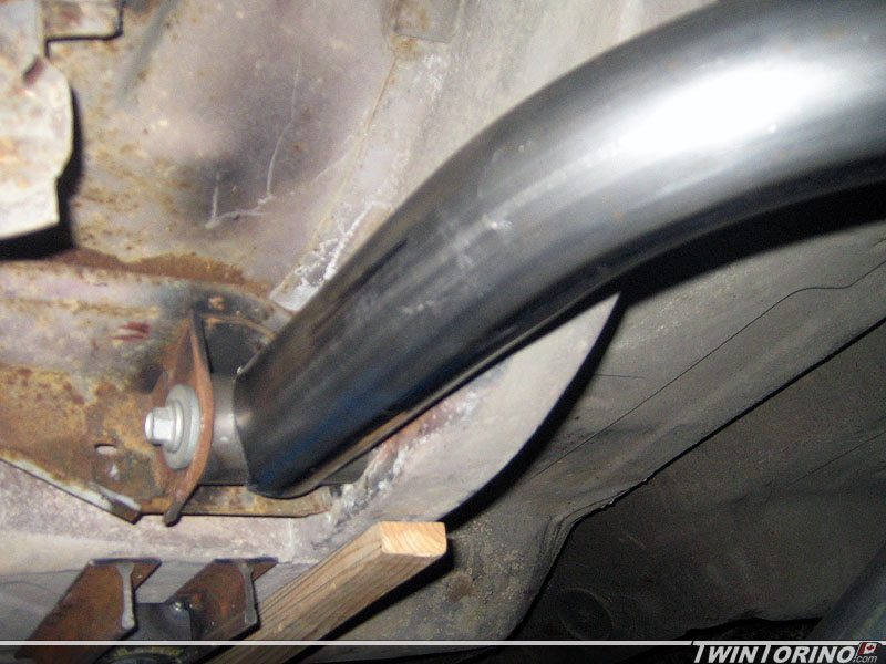
Also have the fabrication nearly complete on the front IRS cradle suspension mounts. As you can see, they tie into the existing leaf spring mount. We cut a sction of 2″ steel and notched out the 2.5″ main tube – worked perfect. Another days worth of work and they will be ready to weld in. Getting closer to getting the car down on the ground. We decided to rigid mount these instead of using rubber bushings like the factory ones.
Mustang Suspension Parts Stash
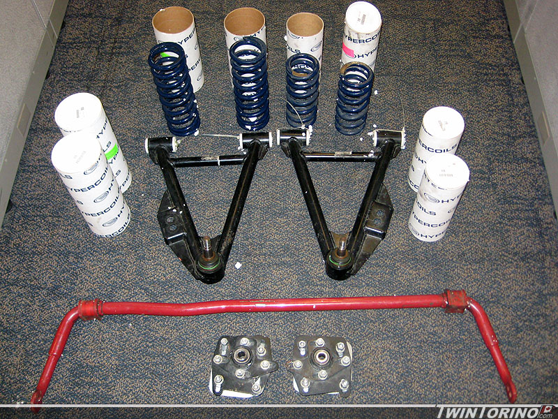
Managed to find several more Mustang performance parts (used of course) from one person that almost completes the parts needed to finish the suspensions for both cars. This includes 4 sets of Hypercoil springs (2 1/2 ID front, 2 1/4 ID rear), Maximum Motorsports tubular lower control arms and caster camber plates, and rear Eibach IRS swaybar (29mm). Almost there – can’t wait to take the first lap around the track!
IRS Bends and New Oilpan..
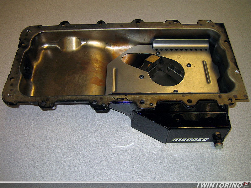
Starting to order up some of the parts required to rebuild the engine (or at least check it out) and then add part like oil pans that are spefically for road racing. We decided to get a Moroso pan that is specifically designed for use during on track events and has seprate trap doors to keep the sloshing to a minimum.
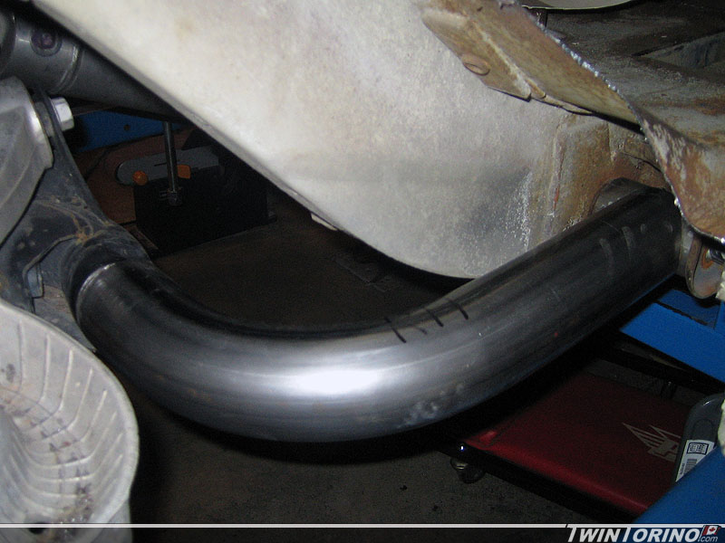
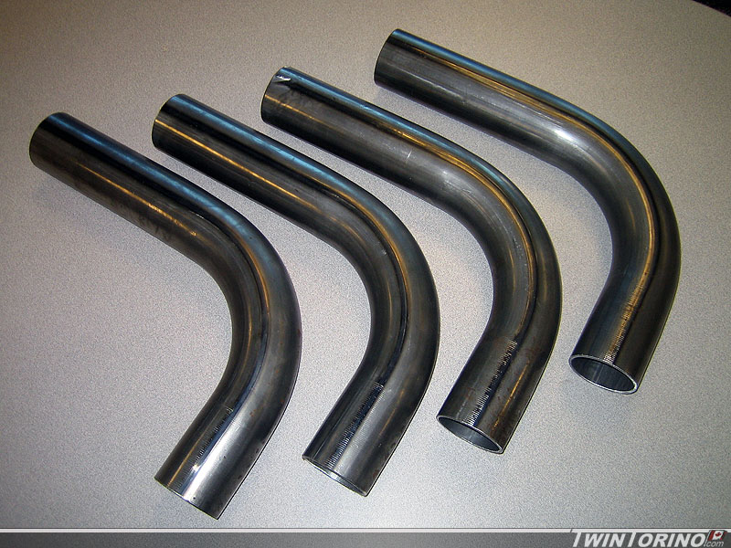
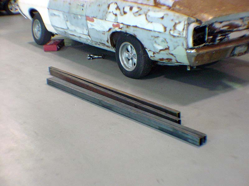
Also had the IRS tubes show up today which will allow us to complete the rear suspension install. These are 2.5″ x 1/8 wall tubes we had custom CNC mandrel bent for this application. They came out great as you can see.
Suspension Simulation..
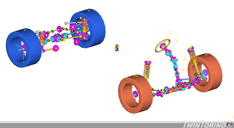
We have been spending some time lately figuring how we want to set the suspension up, and seeing what we want to run for hard points on the chassis etc. We also want to figure out how to set up the rear springs/shocks, since there is not a lot back there. We started to get the chassis points into the computer and figure out roughly how the car will behave when we set up the points the way we want to. The models is being created using program called Motionview (by Altair Engineering) which is for multibody dymanics. This is then sovled using a program called ADAMS.
Here is the model as it is today. The front and rear suspension have all the basics points in. Not much to see aside from the bare basics. You can clearly see all the main suspension parts for the front MacPherson strut suspension and SLA rear IRS. The key here is the info it spits out.. and not having detailed graphics. I will post some animations once they are up and running, as it makes more sense when you see things moving. Now it is time to determine the kinematic behavior of the car (camber/caster/toe curves) and them move onto the dynamic side of things (spring rates, shock rates etc). Also been spending some time with a complete 3D rendering of the car which should be ready to post in a week or two.
This is much easier to do now before everything is finished, and it is not really easy to guess how a car will behave by just looking at where points are. This will provide a starting point for setup, as it is much harder to move points when everything is welded in for good.
Making the Floors Go Away.. Adding Some Stiffness..
That’s the story.. now some progress.
Floors be gone:
Soon to be subframe connectors:
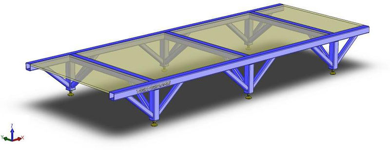
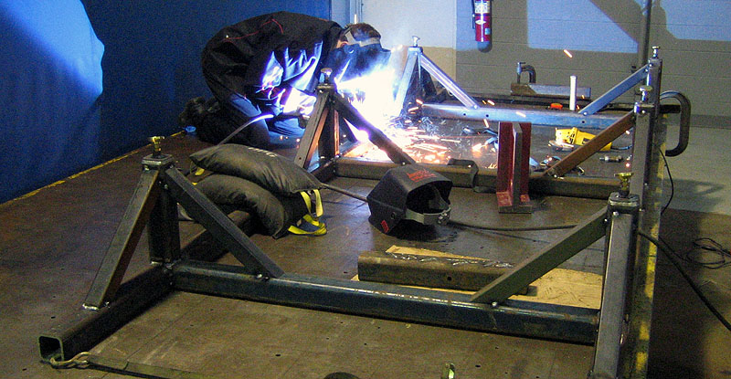
Custom chassis fixture for setting up suspension and powertrain:
IRS cradle fixture:
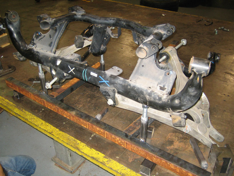
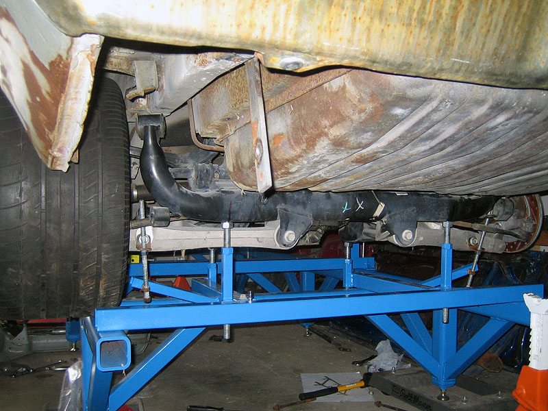
IRS moving into place..
Finally starting to get some useful work done on the cars after all the detours of project funding, fixture building a parts sourcing. It has been a long road that has brought us through many provinces and states.
Making Room for the Rear Suspension
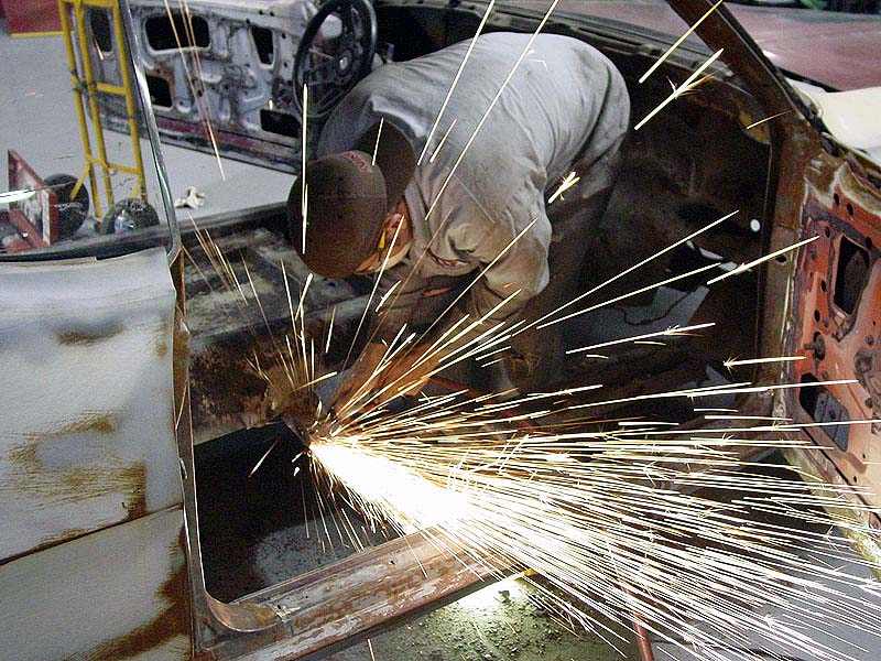
Since the 315 or 335 tires will not clear the inner wheel wells, we needed to make some more room. The suspension will also move differently than a solid axle (you get camber change now with the IRS), so that further defines the need to minitub the rear of the car. Since there is no kit available – we need to just cut out an inch of floorpan and add an inch to the inner wheel wells. Finally got to put the plasma cutter to its first test – is worth its weight on gold during this step. It is very easy to cut straight lines this way too.
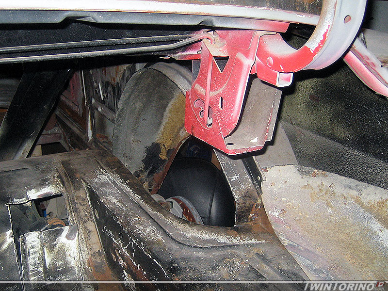
Had to cut holes in the trunk floor so the upper control arms on the IRS would fit. Also hitting the pinion snubber and will hit the jounce bumper brackets, so those were cut off too. This all needs to be done so the car can have a lower stance and still sit at the correct “design” position as it was designed (and not just at some arbitrary control arm angle).