More Rostisserie..

Made some progress on the rotisserie and the car. Most of the parts arrived for the rotisserie by the time Friday rolled around. Got a good portion of the cutting and drilling completed over the weekend and started into welding it together. Goes pretty fast once you get into the groove. Hope to have it up and functional by this weekend. Need to get the car back on the ground – it has been too long.


Rotisserie Begins..

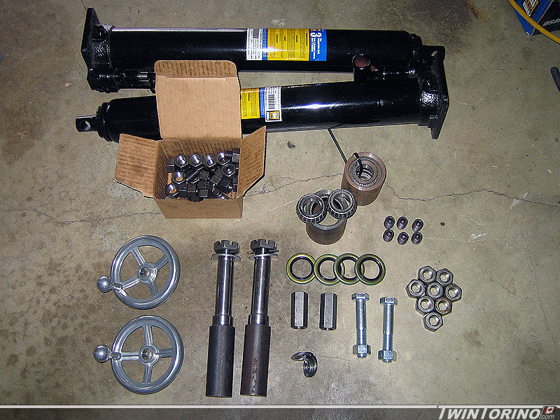
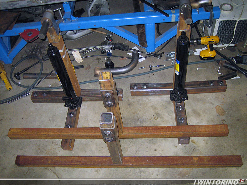
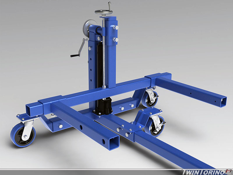
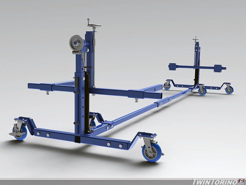
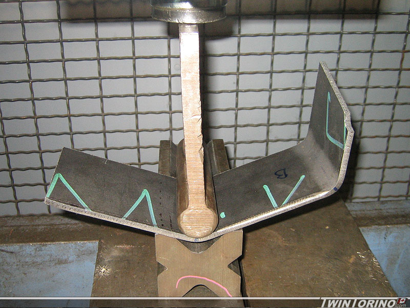
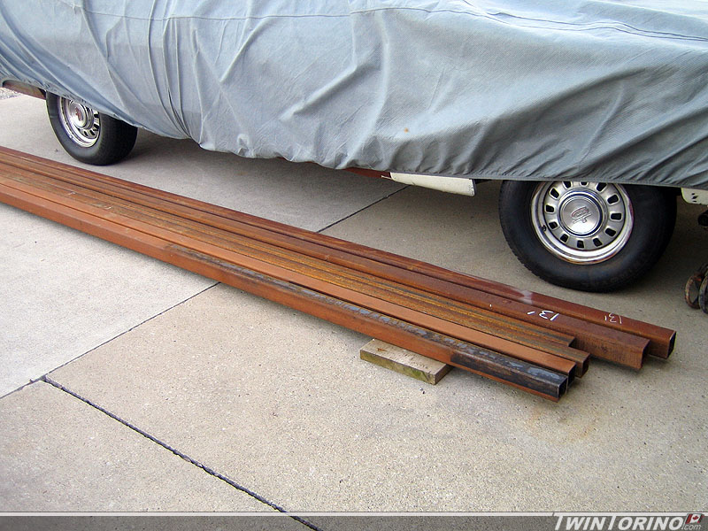
Hoping to build a majority of the rotisserie this weekend. Picked up the steel last Friday, and the rest of the parts and pieces should be here by this Friday. Managed to find an auto supplier that had excess steel from jobs that had been cancelled so got it for a good price. Got some 3″x3″x3/16″, 2.5″x2.5″x3/16″, and some 2.5″x2.5″x1/8″. I already had the 2″x2″x1/8″, and that covers everything besides the plate.

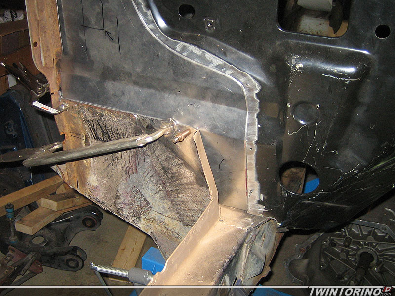
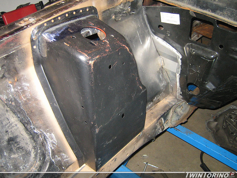
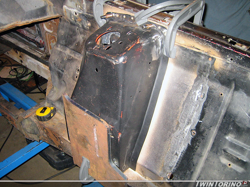
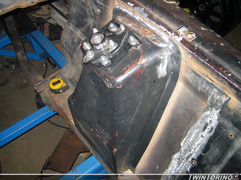
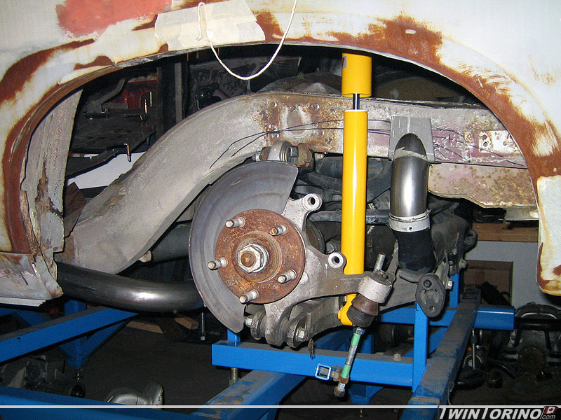
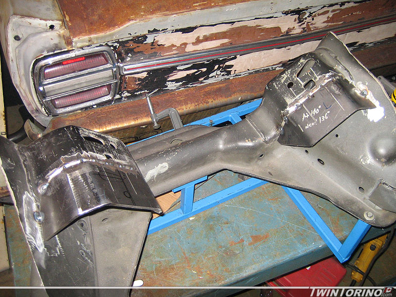
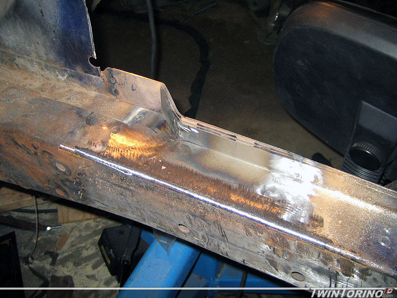
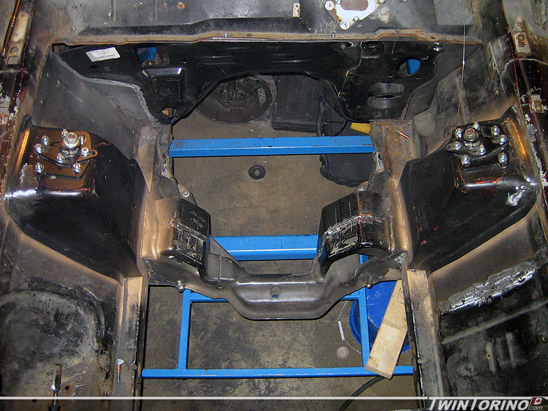
Hit a major milestone over the weeked – front k-member is now welded in and the strut towers have both been finished off. We verified the caster and camber settings, and once we established they were correct, it was welded in for good. Front suspension is now ready to go on the ground! Just have to weld up some of the seams once on the rotisserie and it will be a done deal on the front.

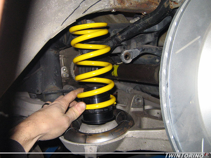
Sway bar is the only thing left. Will be using a straight splined bar from Speedway Engineering with offset sway bar arms. Will use a PVC pipe to package one in for now until the bar rates are selected. To select those, final springs rates need to be selected, which is waiting on the overall corner weights of the car. Won’t have those for a while.

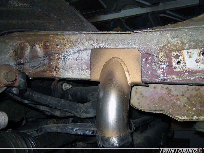
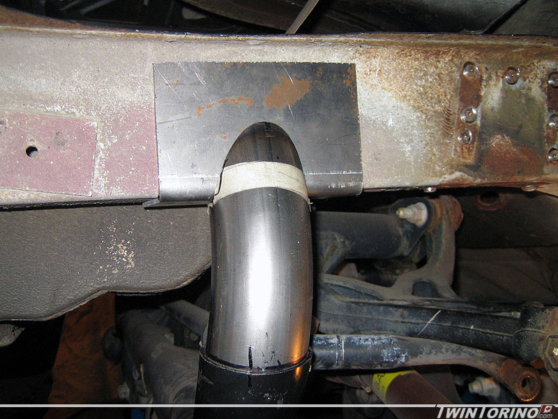
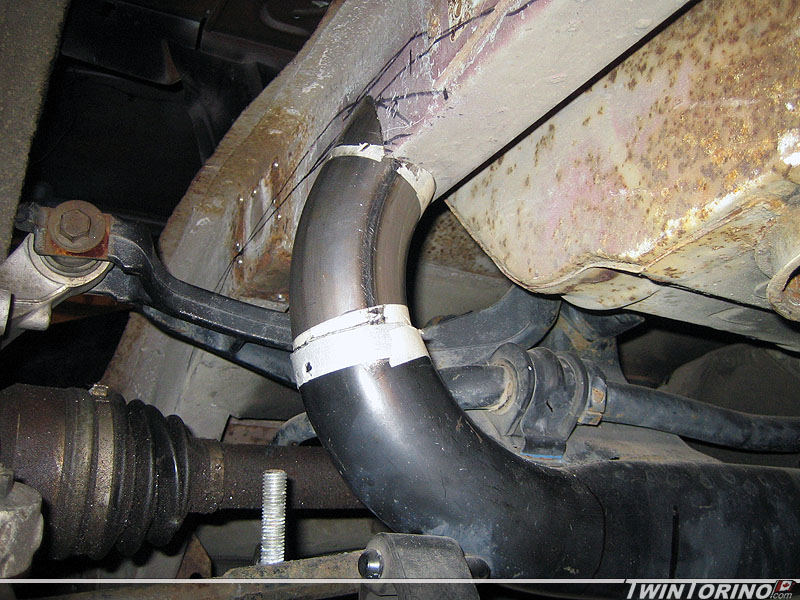
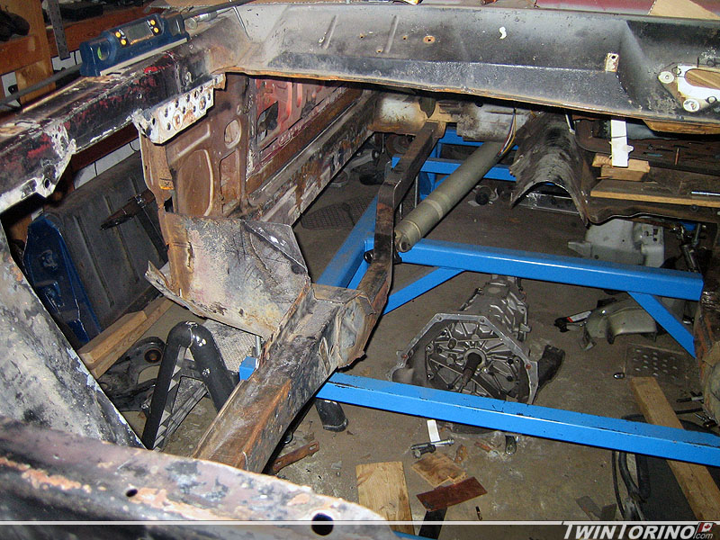
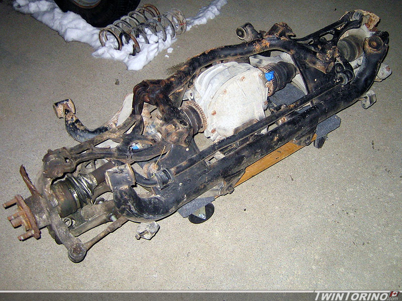
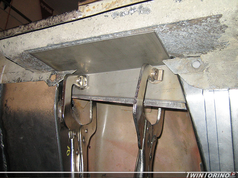
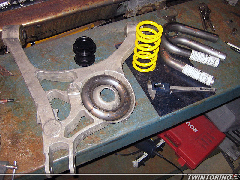
The push is now on to get the rear on the ground. We cut the rear mount to size and welded the tube to it. Just need to drill holes through bracket and frame rails, weld in crush sleeves and weld the tube to the IRS cradle. The front mounts are also done and just need to be welded to the IRS cradle. After that it will bolts right up to the frame in the rear. That leaves the shock mounts and springs mounts which are also nearing completion. Looks like we will be on the ground soon. Just need the rotisserie done so we can pick it up of the chassis jig and put it back down on the ground.

Final rotisserie rendering..

Hand crank will easily rotate the car once you get the cg positioned in the correct place (that’s what the hand wheels at the top do). Otherwise you would just rotate it manually by hand with little effort. Worm gear drive is nice because you can’t backdrive a worm gear. Adds another element of safety.

I am hoping to have it up and running within the next 2 weeks. Going to grab all the steel on Friday. Casters showed up today, and found the worm gear winch I need locally on Craigslist. Just need to order up the misc fasteners etc. Still lots of cutting and bending to go first.

Decided to increase the tube size since the initial design as I noticed almost every other rotisserie on the market uses 3″ tube. Just need to tweak the bolting set-up slightly to make it easier to set up. Also narrowed things a bit so it will easily fit into a 4′ wide pickup truck bed. When I got the casters – I looked up the manufacturer and they had the CAD model on their site so I stuck those in the model too see see how much clearance I need for them to be able to rotate.


Rotisserie ready to build

Made some more progress on the front suspension/firewall. Pass side firewall is now near completion and mates up nicely with the torque boxes (easier said that done). After that, the rear closeout was welded in for good, and then the strut tower was tacked in too. Will finish welding up the tower and then weld in the k-member this week. After that – front suspension is basically done except for the swaybar setup which should be fairly easy anyway. It will be based off a Mustang one.

Moving on the rear IRS once again, we bent up some 1/8″ brackets for the rear mounts. Have the pass side mount almost ready to go. Just need to get some crush sleeves made up for the frame and these will be ready to weld in for good. May be hoping in getting the car back onto the ground for the end of the month. This means car #2 can begin. This also leads to the next step which you can see below.

Almost ready to build the rotisserie. Finally have the design near complete. Casters are ordered, I have the hydraulic jacks from when they went on sale last week, and also have a bearing/housing setup that I found kicking around. Just need to grab the steel. Rotating part is based on a std. trailer spindle which make things cheap and easy to find parts for. Also makes it easy to seal things up for bringing near the sandblaster etc. We will just run dynamic trailer seals on both side of the bearing. Worm gear setup on the end is from a Harbor Freight winch. Made this up in Solidworks 2010 – CAD sure has come a long way. Have this designed so it will pick the car up off the chassis fixture (remove the center section and add the 3rd set of wheels).

Shock towers in.. IRS continued

Couple more updates..

Finally stuff on the front suspension is going in for good. Final prepped everything on the drivers side strut tower, drilled all kinds of holes for plug welds and welded everything in. We will wait until we get the car on a rotisserie to well all the way from top to bottom. With the plug welds ground down, it looks like the pieces were supposed to be there. Just need to weld in the pass side and it will be time to put the k-member in for good. Almost done with the front – hard to believe.


On that note – time to catch up on the back suspension. Finally decided how to do the rear mounts on the IRS. We used one of the 2.5″x1/8″ tubes we have made up for the front mounts, cut one in half and will use the 2 pieces to make up both rear mounts. We lucked out and it looks as though the rear tubes use the same 5″ radius as our bends do. Big thing is the rear mount will still clear the 315’s with stock wheel lips. Just need to go grab some more steel to make up the actual brackets that bolt to the frame as we used a scrap piece for now that was a bit too small. Next we need to make up pockets in the frame for the shocks and clearance for the upper control arms. We’ll be on the ground in no time.


Hole through the car..

Started pulling everything apart before the re-welding begins. This one definitely screamed Kodak moment. This is a close to a skeleton as it will go. Will be a nice picture to look back on. The car sure looks bad like this :). Thankfully this will now fill in really quickly.

Finally have the drivers side strut tower completed and ready to weld in. Got the stiffener plate welded on and have all the close-out panels welded in and ready to go. Hope to finish the pass side one this week and get them welded in for good. Only a year behind schedule on these :).

Stashes and Front Suspension..

You never know what you will find on Craiglist.. that is for sure. Responded to an ad for a Mustang rear suspension and a couple of hours later.. ended up with another Cobra IRS in the driveway. This one is out of a ’99 Cobra (28 spline inner/outer axles). Not sure where it will go or what to do with it.. but it will find it’s way into another project – no worries there.

Got the motor mount extensions tacked in and ready to go. Likely won’t go much further with these or drill motor mount holes until the actual engine goes in and we can check clearances. That way it can go back as far as possible. To do that we will just cut the studs off an old set of motor mounts which will allow the motor to easily slide back. K member is now ready to weld in. Just need to finish up the strut towers are front suspension will be almost done.. finally!

Started working on the strut tower stiffening braces. These will directly tie the strut towers to the upper “shotgun” pieces on the body. These tie into the reinforcements plates on the Mustang strut towers.

K-Member Engine Mounts and Wiring

Moving right along – have the Mustang K-member mounting tabs completed. Only thing left to do it shift the engine mounts back 3″ to get the engine as far back as possible. Since the steel on the stock mounts is 3/16″ thick, this means the std brake won’t cut it. Have to move the the hydraulic press for these bends. Got them ready to weld in over the weekend. Will get them welded in this week and then it is finally time to weld the front suspension permanently into the car.


Also found a complete vehicle wiring harness set from a Mustang GT and heater box / ducting parts.

Frame Repair and Rear Suspension Continued..

When we removed the shock towers the steel was flaking away a bit, but I thought it was nothing out of the oridinary. The more I picked away at it.. the bigger it got. Have to attack this before the towers go back in. Should last a couple more years now. This also brings up the question – how the heck do you get at this area if the stock towers are still in the car? Most people do not have the novelty we do by not having them in the way. Still have to fix the underside where the rest of the water went and rotted things away.


Since the front suspension is finishing up, time to move back to the rear once again. Had a lot of time to think about this one now, so time to put it in action. Biggest issue with designing anything in the rear is the tire clearance. Fitting the 315’s back there requires lots of room. Couple of constraints here – the outer fender lip since the tire will sit within it, the springs and the shocks. We went back and forth on coil over shocks, but in the end they are expensive and take up precious tire clearance. They also do not provide the most desirable load path as the shock mounting holes are outboard of the frame rail (many of the aftermarket kits out there use single shear mounts on the outside of the frame rail which we are not big fans of). The shocks even without the coil-overs will require notching the frame, although very minimally. The result here.. the springs and shocks will mount in separate locations like the stock Mustang.

In the end, this is how we decided to mount the spring. We are using the stock spring pocket on the lower control arm, but using a much smaller spring. We started with 2 u-bends as you can see, and turned them into a doughnut. This way we maximize surface area to distribute the load. Just need to add a flat plate in the middle and a small wedge to angle the spring as required. Then we simply add a mount to the frame rail. Notice we are also adding an adjustable sleeve for fine tuning the ride height. Since we are running fairly stiff springs all around, we will be using helper springs (very low stiffness) to keep the springs in place when the suspension goes into full rebound.


Engine Cradle Continued

Couple more updates from the past week.

Finally found a steering wheel for the cars.. been looking for a while on this one. Two reasons for this choice: the style is “somewhat” similar to the original with the single horizonal bar, and secondly Sparco has been clearing out some wheels on Ebay cheap so this made them affordable too. We’ll see what it looks like in the car I guess. The model is called “Veloce” and is leather with the perforated leather strip at the top.

Moving right along on the front suspension. Pass side strut tower is done and ready to tack in. Next step was to make a perfectly centered and tight fitting k-member. The one we have been using to date is hacked up and really only for setting things up. Time to make another jig for this. As you can see, nothing too elaborate, but it serves it’s purpose. We used reference holes on the part used at the assembly plant to locate the jig. Then we made up 2×4’s that are the exact width between the frame rails. Finally two pieces of plywood are used to conform to the curves of the part. To use, the jig is placed on a Mustang K-member, sockets are placed in the 4 holes to located jig and then a utility knife blade is used to scribe lines on the parts. After that, we break out the plasma cutter and trim/grind to suit. Works like a charm! Making one for car #2 is now a breeze.


We used it to cut the k-member shown and it fits perfectly. That will make it very easy to weld in. Started on making up pieces to run under the frame rails to clean up the package and add a bit more stiffness. Kinda looks like the k-member was meant to be in there. Just need to make up the rear ones and the k-member will be ready to go in. Only thing left now is to weld in the filler panels and modify the motor mounts. After that, the front suspension is done!!


Page 6 of 12« First...«45678»10...Last »

Categories

Archives